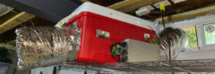
What is that I see above? That’s ASIC 28 on an L3+ hash board. You probably can’t tell what’s going on here, but I’ll attempt to explain why the image above is bad and I promise I have a better one below.
I was working on a hash board that showed the infamous “0 asics found” and eventually, through blood, sweat, anger, hunger, and tears found that ASIC 28 was actually bad and wound up affecting the entire hash board. Sometimes the ASIC tester points to the exact cause, but most of the time it’s just you, a multimeter, and a worthless $200+ hash board test jig.
Let’s fast forward to me soldering on my first DFN (dual-flat no-leads) package. At first they look intimidating, but once you get the hang of it they’re actually quite simple to put on. The only thing you have to worry about (which bit me in the end, hence why I’m writing this) is that if you don’t have enough solder on the power and ground pads, you won’t get a good enough connection for the ASIC to function.
I followed a few videos online (from Antminer Repair) to learn the basics, but since I didn’t have the fancy solder stencil, I was forced to do my favorite thing, improvise.
I started the painstaking process of removing the old ASIC, which can be a problem itself. Bitmain doesn’t use a low temp solder so you really have to heat things up for a while before the ASIC will give up its death grip. Unfortunately I did a little damage to the PCB (printed circuit board) when removing it, fortunately it was a NC (no connect) pin. You’ll also want to remove the heat sinks from the ASICs around the one you’re replacing so you can get some room to work. About 30 seconds from a heat gun is enough to pop these off easily.
 is a NC (no connect) and on the side you see some copper showing from me prying the old ASIC off.")
After following the advice from Antminer Repair on Youtube I tinned both the pads on the PCB and on the ASIC itself. I then placed the part on and heated it until it self aligned and slowly held it in place until the solder hardened. Sounds way too simple, but easy day, right?
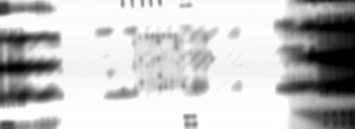
After cooling and cleaning I went and plugged the hash board in, nothing, “0 asics found”, I was defeated. I broke out my multimeter and started measuring all the signals (RI, RST, CLK, BO, and CO.) I even measured out the resistance between pins and pads to make sure I hadn’t damaged anything. I was at a loss. Finally it dawned on me, maybe there’s poor connections from the ASIC to the PCB. I don’t have x-ray vision, so I got the next best thing, an actual x-ray.
 with poor connection to power and ground due to me being skimpy with the solder.")
As you can see, or maybe not, look at the ASIC above and below, there is a large solid mass where the power and ground planes are. Now look at the one in the middle, not so much. My aha moment was here, without proper power and ground this puppy wasn’t going anywhere.
I reflowed the ASIC and removed it, added a bit more solder, and viola, 72 ASICS found, my dream come true.
Don’t skimp, don’t be cheap, and practice practice practice (or do what I’m going to do in the future and pay a professional.)