What’s my fans CFM and how do I measure it?

Part of managing your crypto miner is finding the perfect balance between performance, power usage, cooling, and noise. It’s not often easy, or even fair, how the balance works out. Often times I find myself sacrificing hashing power in favor of cooling and noise (happy wife happy life…)

So let’s talk about that, cooling and noise. Is there a way to pull this off and still keep a reasonably high level of hashing? Short answer, of course yes, long answer is still to come.

I did a little research into the actual air movement with respect to fan speed, and threw in some sound data (db @ 3″) for fun. I didn’t include temperature data because all hash boards and all systems running at all different voltage levels would just add too much confusion into the data (which may already be confusing enough!)

The test data was from a stock L3+, 4 hash boards running at 384 MHz (504 MH/s), using stock 6000 RPM fans, and I ran the fans from 20% speed to 100% speed (set in the firmware.) Each measurement I ran I took 3 different times after resetting the speed in the firmware. This gave slightly different results each time. One dataset was significantly different then I realized my measuring point was off for that set so I tossed it. The CFM was measured at one corner of the intake and exhaust where I saw the greatest volume. I measured the sound (db) at 3″ since I have other miners running and much further out from that it modified the experiment too much. 3″ allows us to track the trend of sounds with respect to fan speed, but won’t give you a relative db level to explain to your family why your basement/garage/shed/man cave is so loud.

Below are graphical reports of the data I collected. What I found most interesting was the actual CFM that I measured the fans at. As you can see the CFM drops off as the RPM drops off.

This is a basic and straight forward view, but to understand the relationship of CFM to RPM I normalized it versus 100 RPM. Basically this tells us that the relationship is directly proportional, i.e. speed up the fan 10% and you get 10% more CFM.

Now what about noise? While we all care about the last two graphs, mama and the family really only care about one thing, noise (two if you count money but I didn’t collect data on happiness versus profitability yet…)

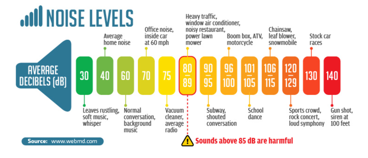
What the chart shows is that you have a significant drop in noise going from 6000 RPM (100%) to around ~3700 RPM (50%.) First off, I know 3700 isn’t 50% of 6000, but that’s up to Bitmain and how they wrote their firmware. But what it does tell me is that if I can tune my boards so that I only have to run around 3700 RPM then I’ve turned my indoor gas lawnmower into pleasant office noise (and minimized my chances at even more hearing loss.)

noiselevelchart

Also, one bonus chart, ever wonder how to relate fan speed % to RPM in the firmware, here’s what I came up with. While actual RPM did vary slightly, it didn’t seem to vary more than 1% each time I set at each specific fan speed percentage.

The big thing to remember as well, the speeds and CFM (not the db necessarily) are based off the fan manufacturer so these values are good on any miner that uses this stock 6000 RPM fan.

Hope y’all find this useful!

What to do when you can’t fix an ASIC chip on an L3+ Hash Board?

Bypass it, jump over it, leave it in the dust, at least that’s a path that I decided to go down. I was having problems with ASIC 28 on a hash board, and due to (most likely) a lack of skill in soldering I was unable to fix it, Before I caused more damage I decided to write it off, not the whole board, but the ASIC itself.

After looking at the schematics and understanding how the L3+ hash board works I had an epiphany, why not just skip it. The via’s are already there to run the wires from, I wonder…

The firmware doesn’t disallow a board to run without all the ASICs, it just checks that they are present and reports data from them. If it’s not there, it skips it and moves along. So how did it turn out? Spoiler alert, it works fine, just some patience, 30AWG wire, and a soldering iron is all it took.

Bypassing a bad ASIC on a Bitmain Antminer L3+ hash board

How to know if it’s a bad 14V boost circuit or bad LDO’s

I’ve always heard the first thing that fails on an L3 hash board is the 14V boost circuit, I can say that I 100% agree with this. Of all the hash boards I’ve repaired, at least 75% have been fixed by installing an external boost circuit. Normally this problem is evident once you measure the voltage across D1 (anything less than 14V spells out a problem), however sometimes that voltage can be deceiving.

I recently worked on 3 different hash boards that came on two L3+ systems I bought off Ebay. The sellers were clear and honest about there being a bad hash board or two, so I knew what I was getting into. Two of the boards measured over 14V at D1, which normally would tell me the boost circuit was fine, however I now know it wasn’t. The other was more telling, 10V at D1, popped a boost on it and it’s been hashing away fine.

After measuring 14V at the boost I proceeded to measure all other relevant voltages on the hash board, that includes not only checking 14V, but the 10V from the buck controller (measured at L2), 12V input to the board, and the voltage across pins 2 (GND) and 5 (1.8V output) of each LDO. The first 10 domains measured correct at ~1.8V, however domains 11 and 12 came in at 1.1V and 0.5V respectively. My go to was to try and replace the LDO’s since that’s a common failure, however this time it didn’t fix them.

Note – The LDO’s at the last two domains require an LDO that takes a higher input voltage (~5V on 11 and ~4.5V on 12.) Some versions of the LDO work across a wide enough input voltage range that they can be used on all domains, however the most common (LN1134 marked usually as 4VK4) only works with the first 10 domains. This device only works up to a 3V input and will fry if you put it on the last two domains.

After failing to fix the problem my first thought was, “what if, under load, the 14V is dropping.” This would point to the common problem the on-board boost circuit has, and even the inductor (L1) can’t help keep the voltage constant when the output current is less than the draw of the LDO’s. So I popped off D1 (to isolate the on-board boost circuit) and installed an external boost circuit.

I plugged in the hash board, viola, it came right up and started hashing away. I went back and verified the voltages at the last two LDO’s and they both measure a clean 1.8V output. I put together a quick video to show the steps I went through:

https://youtu.be/5abmjlW9_4I

Lesson learned, even if the boost circuit says ~14V, it doesn’t mean under load this isn’t dropping. You really can’t fully test this unless the board is actively hashing and the LDO’s are drawing current from the on-board boost. If you measure 14V but don’t get 1.8V from the last two LDO’s, consider it might be the boost circuit instead of bad LDO’s, or even both…

Inside the Antminer L3+ Hashboard

One of the challenging things with working on an L3+ hash board is the lack of a full set of schematics or gerber files available for the printed circuit board (PCB) to figure out the full function of the board. I’ve reached out many times to Bitmain but it’s not high on their list to release, guess they don’t want anyone reverse engineering the board…

Where does that put us, well, luckily the L3 has a huge community of folks constantly working on the hash boards and reverse engineering the board. RDC has done a great job of putting together schematics of some of the things the Bitmain manual lacks.

I also decided to dive a little deeper, with that I mean inside the board. I attempted to x-ray the PCB, hoping to gain a little more insight into the trace routing. The issue I ran into was the resolution of the x-ray and the energy put out was too high, washing a lot of it out. If that makes little to no sense, it’s like trying to watch an HD movie on an old tube TV. Regardless, some good came out of it and if you zoom into specific areas you can see some of the traces running to various points.

X-ray of L3+ Hash Board

I built a high res video that shows the location of all components (and silkscreening on the board) for both the top and bottom. I will make the raw files available as well since it’s near impossible to find top side components without removing heatsinks. Luckily I have my practice board available…

Layer 1 of L3+ Hashboard PCB – Courtesy of RDC
Layer 2 of L3+ Hashboard PCB – Courtesy of RDC