I’ve seen a lot of posts lately, and even got an message or two, asking how I remotely monitor my L7. Since (as of 8/12/22) there isn’t any after-market firmware available, nor would I suggest using any while your system is under warranty, some hacks and work-arounds are needed.
That solves the remote login issue, but what about alerting you when it’s down? There’s scripts you can write that can verify pings every so often, and that will tell you if it’s alive. But what about if it’s hashing?
To solve that I look at it inversely, I want my miner to tell me it’s down, but if that’s not easily available, then I want it to tell me it’s working. So how can we do that? It’s not as hard as you might think, in fact it’s a quick and easy hack. First, this will depend on what pool you mine and what the payout interval is. For example, if you use Litecoinpool you can set a payout threshold to meet a time interval of roughly 4 hours. For Nicehash it just happens every 4-6 hours. Why is this important you might ask?
Now let’s look at your wallet. Pretty much every wallet on earth allows you to receive a notification when you receive a payment. I have a wallet that I use for mining that I have an alert set for any incoming payment. So, knowing I have a payment threshold of 0.1 LTC on Litecoin pool, for one L7 I expect a payout roughly every 5 hours. If I don’t receive a text alert every 5-6 hours from my wallet that a payment was received I can login with VNC and verify that I’m still hashing.
Is it perfect, no, but it works for me and was a quick and easy hack to make sure I don’t have to constantly login to monitor miners. I know there are better hacks, feel free to share, that’s what this community is all about!
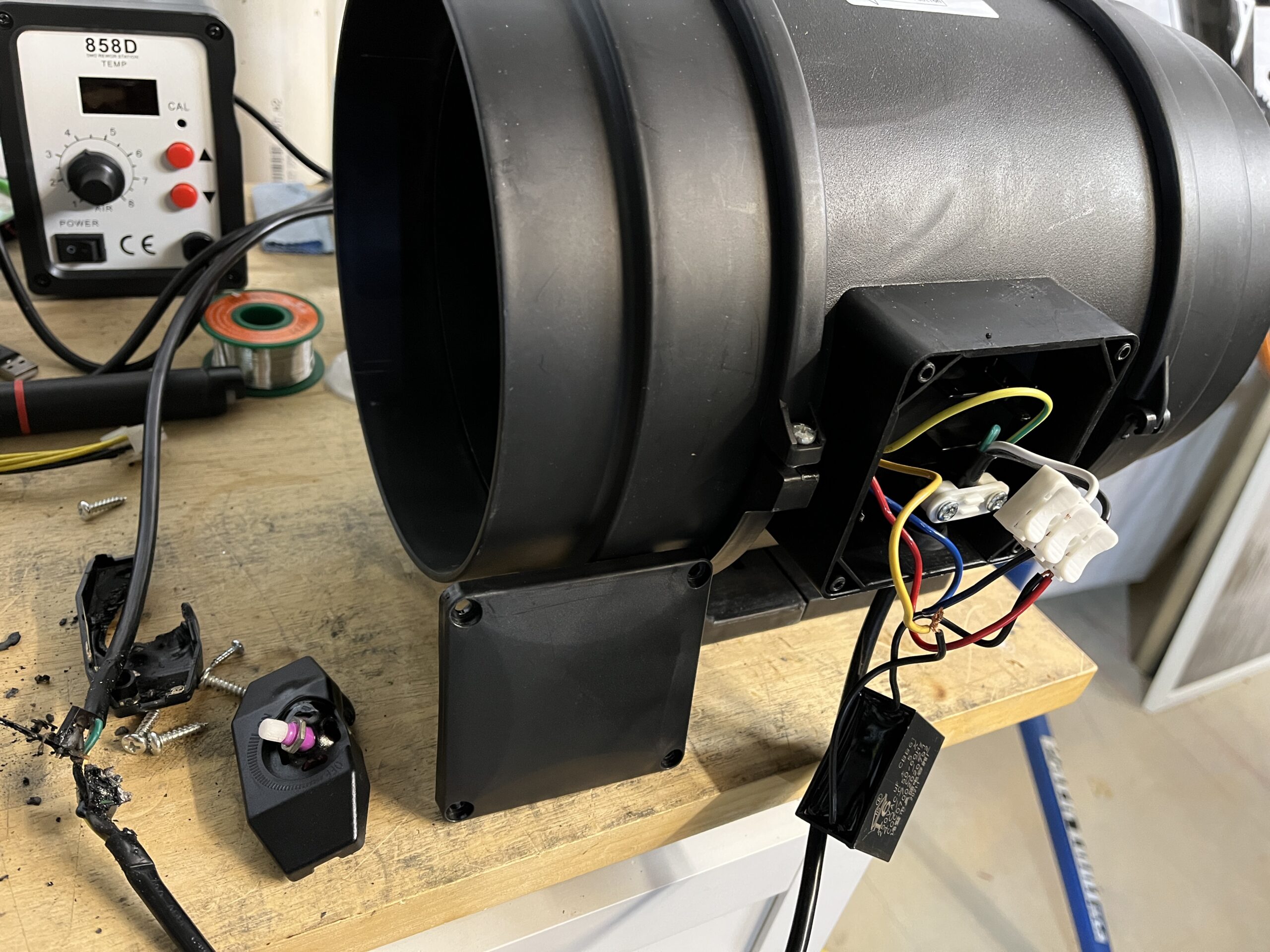
How is that for a headline? Certainly nothing you ever want to read or even think about. As you can imagine, I feel very blessed and lucky that the circuit tripped before anything worse could happen, but it’s a very good lesson to learn. Mainly, always inspect you equipment, don’t buy cheap unknown knockoffs, and use circuit protection for everything.
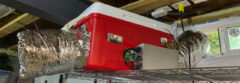
So what happened? I was gone for a few days on a work trip so I can’t say the exact time this happened, but I can ball park it since the duct fan killing the circuit shut down the miner as well. A caveat to that is that the miner only shut down because it has programming to shut it off when it gets too hot, which is another learning point for me.
This happened on an L7 I have and I was using the duct fan as the primary cooling and manually set the fans on the L7 to be at 30% (roughly 3000RPM.) Once the duct fan controller burned out the only thing cooling the L7 was its own fans, which I had set too low to actually cool it, hence it shutting down. Lesson here is that I had no need to manually dial the L7 fans at 30%, I could have left it (and will from now on) at automatic and they simply would speed up if the duct fan ever failed. So what if I had removed my onboard fans like several people have mentioned? There’s more of a risk that you could burn up your hash boards before the software catches them heating beyond threshold (90C I believe on the L7.)
I threw a little video together on my lesson learned and what to watch out for.
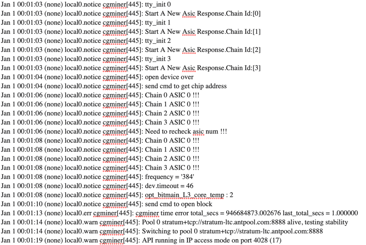
We’ve all had miners fail (if you’re here that’s most likely why), it’s frustrating, maddening, but gosh darn-it, people like you. After you’re done staring in the mirror, it’s time to start figuring out what to do. The number one thing I tell everyone I’ve worked with is to save that kernel log! I mean don’t turn the miner off until you’ve gone into the settings and copied and pasted that log into a file you save. The answer to your question may be in there.
Why save the current log? Well, for one thing that’s the “black box” of what happened. All communications between the boards and the mining pool are there and you want to know what the last thing was that happened before things went awry. Most miners (at least ones I’ve worked with) don’t save the log if you power down and reboot, it will instead overwrite with a new one. There are ways to recover it however, but unless you’re a more advanced user that knows how to SSH in, that’s not something that is easy to walk through.
There are many things that the kernel log can tell us that will point directly to the issue at hand, below are just some of the more common ones (and some uncommon) that I’ve come across:
Chain X ASIC 0 !!!
0 ASICS isn’t always a death sentence.
Another very frustrating error with very little data. Luckily most of the time this is a rather simple fix for being such a vague error. This error essentially tells you that when the control board polls the hash board (via I2C bus) it gets either no response or an improper response from the hash boards PIC after it initializes. Sometimes it will even come back with a number like Chain 2 ASIC 23 !!! which points to ASIC 24 as the specific issue, however a ASIC 0 points to a few things we can try to fix.
CHECK VOLTAGES AT THE 10V BUCK CONVERTER AND 14.2V BOOST CIRCUIT.
Sometimes, more often than it should, the boost circuit on the hash board fails and subsequently asics show as missing or ‘xxxxxx’. Check out my walkthrough manual and scroll to the 14.2V Boost Circuit for more info. Furthermore insure the output of the 10V buck converter matches the voltage you’ve set in the firmware for that chain (i.e. common voltages like 9.5V, 9.8V, or stock voltage of 10.11V.)
CHECK VOLTAGES AT YOUR LDOS.
The L3 has 12 voltage domains, each controlled by a single voltage regulator. Most recently Bitmain used an LN1134 but has used an SPX5205 and SGM2202 in the past. In the past these domains have failed when the 14.2V circuit failed so it’s a good idea to check the voltage at each domain. This can be done by checking the voltage between pin 2 (middle pin on LDO) and pin 1 (input ~2.4V) and pin 5 (output ~1.8V.) Check this at each LDO (i.e. U75, U76, U77…) Check out my walkthrough manual and scroll to power domains for more info.
COLD RESTART THE UNIT.
From time to time intermittent problems like this can be solved by shutting the unit down for 30 seconds and then rebooting. This isn’t a long term fix but may get your unit back up and running for the time being.
LOWER THE FREQUENCY AND INCREASE THE VOLTAGE.
Go into your advanced settings for the problem hash board and try lowering the frequency and upping the voltage to at least 9.8V. Tuning the hash boards to run on minimal speed and power can have the board operating at the edge of its ability to function. Resetting the PIC to a more normal operating condition may solve your problem. Likewise operating at too high a frequency and power can potentially shorten the life of components or operate on the edge of functionality.
RELOAD THE FIRMWARE.
Sometimes reloading the firmware, especially with one that allows autotune, can help isoloate or even fix the problem if it’s with the PIC.
REFLOW THOSE SOLDER JOINTS!
An intermittent connection can change with environmental conditions . Heat and cold can flex cold solder joints and ultimately lead to failures. I’ve found that reheating and reflowing the joints on the temp sensor, buck converter, and PIC have resolved problems I’ve had in the past with missing components.
There are a couple errors that can be associated with fans and they’re pretty straight forward to troubleshoot. The first is below, some older versions of the L3 firmware had this error, most newer and after-market versions don’t however. This points to a failing or failed fan.
Fatal Error: Some Fan Lost or Fan Speed Low!
However as the fans do start to fail, below is the message you may get. For reference fan 1 is the fan plugged into the connector closest to the front of the unit.
Fan Err! Disable PIC! Fan1 speed is too low 390 pwm 44
Fan Err! Disable PIC! Fan1 speed is too low 0 pwm 100
Another thing that points to fan errors is no hashing as the firmware shuts down the hash board if there’s a fan failure to save a thermal runaway condition. Basically, change your fan, eBay is a gold mine for these!
Get Temp Data Failed
This is pretty straight forward and almost always points to a bad TMP451 on your hash board. This error tells you exactly which chain has the failure so you can first try and reflow the solder on the TMP451 (the quality varies) or replacing the chip. I have a link to replacement parts here. The caveat is that this doesn’t always affect hashing and some firmware versions will regularly report this error due to a firmware glitch (per Bitmain.)
Get [1]Temp Data Failed!
Network Errors
Net Err! Frustrating and generally means you’re not making $. Most of the time you may see an error like below:
Net Err! lastest job more than 2 mins! waiting …
This is most likely due to one of three common problems.
You have a poor network connection
Your network cables or router have failed
Your stratum address is entered incorrectly
Number of “x” = 4 of Chain 0 Has Exceeded Threshold (on any Chain…)
This can point to a number of issues. Generally when you see this error in the kernel log that is the point at which the hash board shuts down or, if you have a hash rate watchdog enabled, it will reboot. This is generally due to boards overheating or running too “hot” of a frequency. These issues can generally be remedied by lowering the frequency you’re operating the hash board at.
Scanreg Error
The infamous scanreg/crc5 error can be quite frustrating, but know that the secret to this generally lies in the ASIC chips themselves. The problem generally starts by seeing a series of the following in your kernel log:
bitmain_scanreg,crc5 error,should be 00, but check as 01…..
This is essentially pointing to an ASIC failing its self test. Sadly I haven’t seen a way in the kernel log to point to a specific ASIC, but following my post on CRC5 errors will help you track it down using your multimeter.
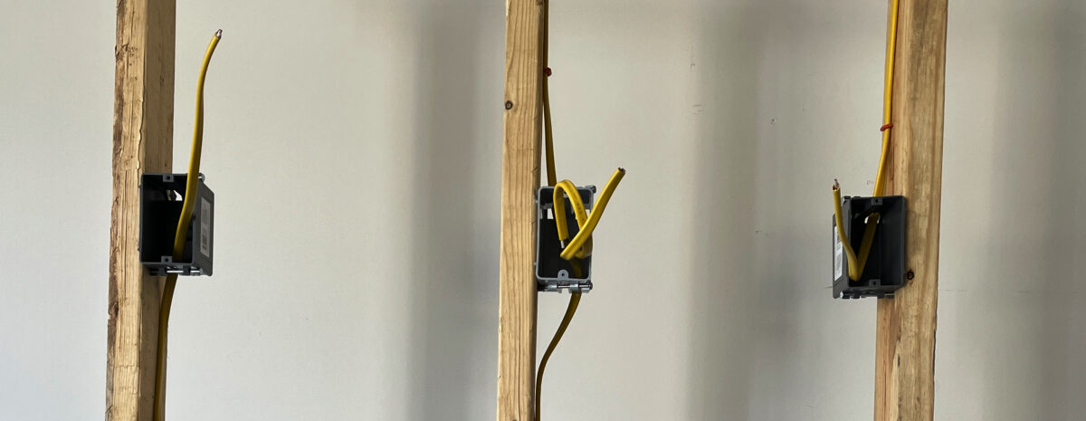
In my series of, “I know what I want to see, but what do you want to see?” videos I had someone ask about the installation of basics 120V or 240V circuits. Well, you got it. I’ve done electrical work for years off and on, that along with some University training should hopefully lead to some useful insight in the below video.
Of note, and a disclaimer, I am not a licensed Electrician, so please consult an Electrician, NEC code, or your local inspector before energizing any circuits. If you’re doing this in your home you’ll most likely need to pull a permit for it anyway, but many areas allow homeowners to do their own work as long as it meets code.
Part of managing your crypto miner is finding the perfect balance between performance, power usage, cooling, and noise. It’s not often easy, or even fair, how the balance works out. Often times I find myself sacrificing hashing power in favor of cooling and noise (happy wife happy life…)
So let’s talk about that, cooling and noise. Is there a way to pull this off and still keep a reasonably high level of hashing? Short answer, of course yes, long answer is still to come.
I did a little research into the actual air movement with respect to fan speed, and threw in some sound data (db @ 3″) for fun. I didn’t include temperature data because all hash boards and all systems running at all different voltage levels would just add too much confusion into the data (which may already be confusing enough!)
The test data was from a stock L3+, 4 hash boards running at 384 MHz (504 MH/s), using stock 6000 RPM fans, and I ran the fans from 20% speed to 100% speed (set in the firmware.) Each measurement I ran I took 3 different times after resetting the speed in the firmware. This gave slightly different results each time. One dataset was significantly different then I realized my measuring point was off for that set so I tossed it. The CFM was measured at one corner of the intake and exhaust where I saw the greatest volume. I measured the sound (db) at 3″ since I have other miners running and much further out from that it modified the experiment too much. 3″ allows us to track the trend of sounds with respect to fan speed, but won’t give you a relative db level to explain to your family why your basement/garage/shed/man cave is so loud.
Below are graphical reports of the data I collected. What I found most interesting was the actual CFM that I measured the fans at. As you can see the CFM drops off as the RPM drops off.
This is a basic and straight forward view, but to understand the relationship of CFM to RPM I normalized it versus 100 RPM. Basically this tells us that the relationship is directly proportional, i.e. speed up the fan 10% and you get 10% more CFM.
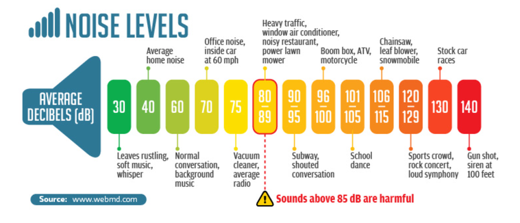
Now what about noise? While we all care about the last two graphs, mama and the family really only care about one thing, noise (two if you count money but I didn’t collect data on happiness versus profitability yet…)
What the chart shows is that you have a significant drop in noise going from 6000 RPM (100%) to around ~3700 RPM (50%.) First off, I know 3700 isn’t 50% of 6000, but that’s up to Bitmain and how they wrote their firmware. But what it does tell me is that if I can tune my boards so that I only have to run around 3700 RPM then I’ve turned my indoor gas lawnmower into pleasant office noise (and minimized my chances at even more hearing loss.)
Also, one bonus chart, ever wonder how to relate fan speed % to RPM in the firmware, here’s what I came up with. While actual RPM did vary slightly, it didn’t seem to vary more than 1% each time I set at each specific fan speed percentage.
The big thing to remember as well, the speeds and CFM (not the db necessarily) are based off the fan manufacturer so these values are good on any miner that uses this stock 6000 RPM fan.
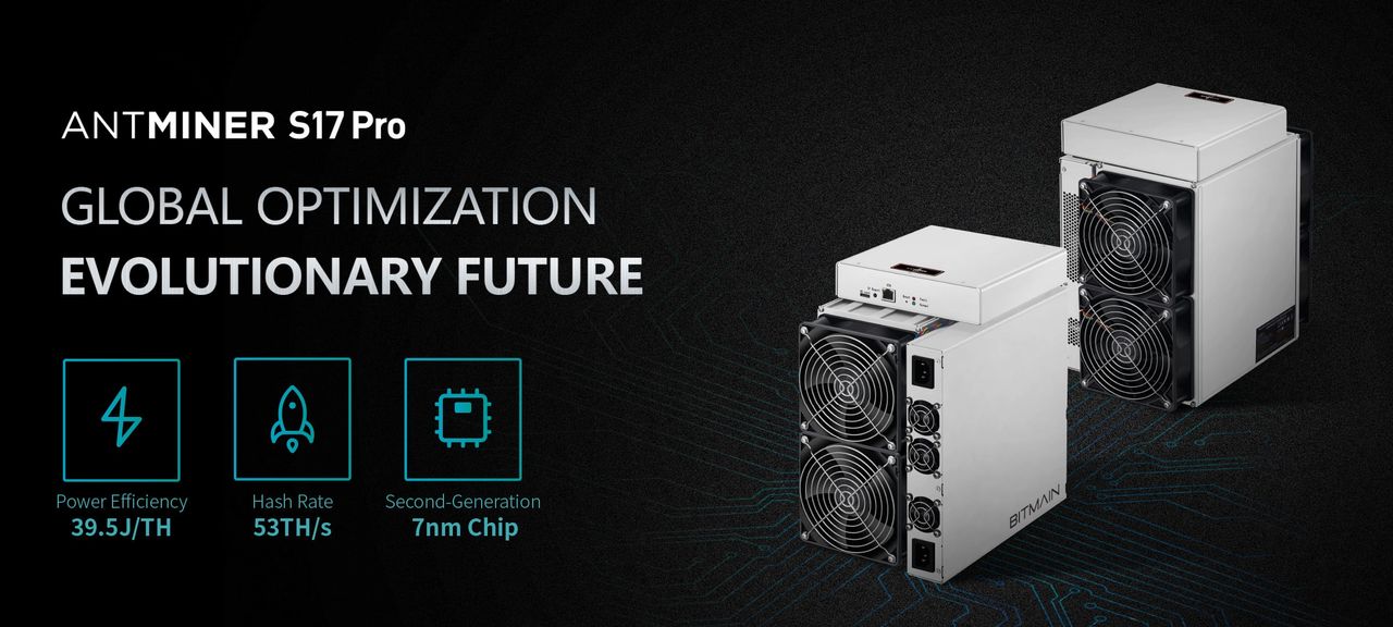
The supposed “dog” of the crypto miners still has a lot of fight left in them. When I first looked at getting the S17 I read a lot of negative reviews, and there were/are issues with them, however there’s also a lot of greatness (and profitability) in these miners. The first point I looked at was cost per TH. The S17 Pro 59TH units I got were roughly $45 per TH. If I compared that to other SHA256 miners it sits near the bottom cost wise (S9 is ~$40-45 and S19 is ~$90-100), that’s good enough for me!
S17 Pro 59TH
Cost – $45 per TH
Profit – $0.20 per TH per day
Time to Payoff – 225 Days!!!
OK, great, I bought a few and got them running. All came up fine but I knew I could squeeze out more. I started looking at available firmware options, which surprisingly there were many. I ultimately decided on several to try; Hiveon, Braiins, Awesome miner, and Asic.to (don’t hate me for missing one of the many others…)
Each had their own unique challenges, whether is was the basic install, having the system properly recognize the hash boards, or the ease of tuning the hash boards to maximize my efficiency.
At the end of the day I went with Braiins. The reason for this was many fold, a great interface, awesome tuning, and easy to use. All things being equal each was easily enough installed, and all cost about the same in dev fees, but the features and performance from Braiins won the day.
I put the process I went through in a quick video, including the quirks that each firmware presents.
What is that I see above? That’s ASIC 28 on an L3+ hash board. You probably can’t tell what’s going on here, but I’ll attempt to explain why the image above is bad and I promise I have a better one below.
I was working on a hash board that showed the infamous “0 asics found” and eventually, through blood, sweat, anger, hunger, and tears found that ASIC 28 was actually bad and wound up affecting the entire hash board. Sometimes the ASIC tester points to the exact cause, but most of the time it’s just you, a multimeter, and a worthless $200+ hash board test jig.
Let’s fast forward to me soldering on my first DFN (dual-flat no-leads) package. At first they look intimidating, but once you get the hang of it they’re actually quite simple to put on. The only thing you have to worry about (which bit me in the end, hence why I’m writing this) is that if you don’t have enough solder on the power and ground pads, you won’t get a good enough connection for the ASIC to function.
I followed a few videos online (from Antminer Repair) to learn the basics, but since I didn’t have the fancy solder stencil, I was forced to do my favorite thing, improvise.
I started the painstaking process of removing the old ASIC, which can be a problem itself. Bitmain doesn’t use a low temp solder so you really have to heat things up for a while before the ASIC will give up its death grip. Unfortunately I did a little damage to the PCB (printed circuit board) when removing it, fortunately it was a NC (no connect) pin. You’ll also want to remove the heat sinks from the ASICs around the one you’re replacing so you can get some room to work. About 30 seconds from a heat gun is enough to pop these off easily.
Luckily Pin 15 (torn pad) is a NC (no connect) and on the side you see some copper showing from me prying the old ASIC off.
After following the advice from Antminer Repair on Youtube I tinned both the pads on the PCB and on the ASIC itself. I then placed the part on and heated it until it self aligned and slowly held it in place until the solder hardened. Sounds way too simple, but easy day, right?
After cooling and cleaning I went and plugged the hash board in, nothing, “0 asics found”, I was defeated. I broke out my multimeter and started measuring all the signals (RI, RST, CLK, BO, and CO.) I even measured out the resistance between pins and pads to make sure I hadn’t damaged anything. I was at a loss. Finally it dawned on me, maybe there’s poor connections from the ASIC to the PCB. I don’t have x-ray vision, so I got the next best thing, an actual x-ray.
ASIC 28 (center) with poor connection to power and ground due to me being skimpy with the solder.
As you can see, or maybe not, look at the ASIC above and below, there is a large solid mass where the power and ground planes are. Now look at the one in the middle, not so much. My aha moment was here, without proper power and ground this puppy wasn’t going anywhere.
I reflowed the ASIC and removed it, added a bit more solder, and viola, 72 ASICS found, my dream come true.
Don’t skimp, don’t be cheap, and practice practice practice (or do what I’m going to do in the future and pay a professional.)
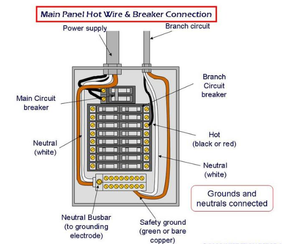
More and more I’ve seen questions from folks about how many, or how big, of a miner can I fit on a circuit. This is a question that has many unknown variables that I plan on diving into below. Disclaimer – Please keep in mind this is my opinion and not an actual consultation for your mining business, so before you do any wiring or make any changes to your electrical system please consult a licensed electrician.
Now on to the good stuff. In order to answer the question how how many/how much we need to know a little more information; the basics of your panel, the basics of your circuits, the basics of the miner, and anything else you plan to operate.
RESIDENTIAL/INDUSTRIAL CIRCUITS
For starters, each location in question needs to have a load calculation done to insure that you aren’t going to draw more than 80% of the maximum panel rating. As an example, if you have a dedicated 100A panel you can’t draw more than 80A continuous at any time. Since the mining world is in watts, let’s use Ohms law to break that down.
100A Panel @ 80% rule = 80A
Ohms Law tells us that Power = Current x Voltage
80A x 240V = 19,200W
So the key thing to keep in mind before planning out circuits is that you can’t have a continuous load more than 19,200W on this panel.
CIRCUIT/LOAD PLANNING
Now that we know the maximum wattage of our panel, we can use a little math to plan out what our circuits need to be. I’ll make the assumption that whatever miner we are using operates on 240V since that’s the industry standard at the power level they operate on.
There are 2 main amperage ratings for 240V breakers that are used in the mining world (yes I know there are more but these are the most common), 20A and 30A. There are several reasons for choosing one over the other, ranging from length of wire run, number of units per circuit, cost of wiring, and available breaker space. The most important thing to remember about each circuit is that they also have a maximum wattage rating:
20A Circuit @ 80% rule = 16A
16A x 240V = 3840W
30A Circuit @ 80% rule = 24A
24A x 240V = 5760W
MINING EQUIPMENT
So we know the maximum wattage our panel will hold, and we know the maximum wattage different types of circuits hold, only thing we are missing is what type of miner we’re running and what its power requirements are.
Since this is February 2022 I’ll choose two scenarios, the first is using a newly released miner, the second is using a couple generations old miner. I’m partial to Bitmain products so I’ll look at the S19 or L7 for one scenario (~3250W) and the L3++ for the other (~900W, don’t hate on my S9 people!)
We know that our maximum panel wattage is 19,200W, so how many of each miner could we theoretically operate (I say theoretical since we have to split this up in to several circuits and the math may not work out perfect.)
S19/L7 = 3250W
19,200W / 3250W = 5.9
5 S19/L7 = 16,250W
So that leaves us with 2950W available in the panel for other electronics, fans, network equipment, etc.
L3++ = 900W
19,200W / 900W = 21.33
21 L3++ = 18,900W
So this leaves us with only 300W available in the panel for other electronics, fans, network equipment, etc. Of course this is only relevant if you plan on running everything for your operation off this one panel.
FINAL CIRCUIT PLAN
Now that we know what our options are it’s more simple at this point, with a little math for the L3++ scenario.
For the S19/L7 scenario it’s clear that we need 5 – 20A circuits, one circuit for each unit. This allows us to dedicate one circuit per unit and keeps us under the 80% rule for the full panel load (we are only using 16,250W which is only 68%.) Unfortunately you can’t fit two of them per 30A circuit like some other units (you’d need to be closer to 2800W to do this) but we have plenty of space in the 100A panel for 5 20A breakers. Keep in mind that 20A breakers will use 12ga wiring whereas stepping up to a 30A breaker requires 10ga wiring.
For the L3++ scenario we use a little math. We can put 4 units per 20A circuit (3600W) or 6 units per 30A circuit (5400W). To maximize the number of units, and keep it simple, we can also go with 5 – 20A breakers, 4 units for each circuit. This keeps us under the 80% rule for the full panel load (we are only using 18,000W which is only 75%.) Once again we will use 12ga wiring for this.
This was a quick down and dirty calculation and please know that there is more in depth planning that would go into an actual circuit design (like run lengths, ventilation, other equipment draw, main panel draw, etc.)
A lot of folks talk bad about the S17, but why I wondered? Before I bought my first unit I did the research and came to the conclusion that it got a really bad reputation based off some poor engineering decisions and poor manufacturing early on. There are 3 versions of this, the S17, S17 Pro, and S17+, each with its own set of issues, but is there a diamond in the rough?
HISTORY
Bitmain first released the S17 in April 2019. There was a 50TH/s and 53TH/s version that ran around 2300W. This first run had a tremendous failure rate in the field, reported from 20-30%. Bitmain at first denied there were problems but early on in 2020 they admitted to having design issues and high failure rates. Two of the biggest issues stemmed from their power supply design and heat sink design. The power supply seems to not be able to pump out the required current to keep the hash boards running properly and the heat sink, well, they were just plain falling off and shorting out the unit (ouch.) Another couple issues that seems to be a common issue across all the 17 series is the units dropping a hash board randomly and bad I/O cables. The dropping hash board may point to power supply issues, but it has gone unresolved. This is fixed by a simple reboot most of the times. Same with the I/O cables. Doesn’t seem hard to get that right, but alas they didn’t.
Bitmain followed this up with the S17 Pro, also released in April 2019. This had a 50TH/s, 53TH/s, and 59TH/s version. The big difference between this and the S17 is that the S17 Pro has a Turbo mode in the settings, allowing it higher hashing power. This model was produced longer than the S17 and the later S17 Pro 59TH didn’t have as many heatsink and power supply failures. This does however have the “dropping hash board” issue that is generally fixed upon rebooting the unit.
Bitmain’s last release was the disastrous S17+, introduced in December, 2019. I’m still not sure what the root of the issues were, manufacturing, firmware, cables, but these were plagued with issues from the start. It was also a power hog at 3000W for roughly 72TH/. Why does that number matter? Well the S17 and S17 Pro all ran under 2600W max, which luckily allowed circuits to be designed such that two units could fit on one 30A circuit. Take that same setup and you can’t cram two S17+ units on the same circuit without overloading it (beyond 80%.) IMHO I wouldn’t have released a version that just went over that number, I would have kept it under 70TH/s so it could have been a plug in replacement (electrically speaking) for the previous generation. There, off my soap box. If you’re going over that, go big, which the next generation S19’s did.
COMPARISON
So there’s our quick history lesson, so let’s bring it in to the main question. Which one is the best of the “average” and what does that look like. After doing my research I settled on the S17 Pro 59TH. I have had a lot of success with this model, albeit I have seen the missing hash board problem here and there. Knowing these were some of the last units manufactured I had more confidence that their processes had been worked out. Additionally I looked at the return based off cost and hashing power.
I started by looking at a more recent SHA-256 miner, the S19 Pro 110TH. If we look at the price per TH we get (based off today’s used prices) $11,000 / 110TH = $100/TH (I love clean math.) Keeping apples to apples we get the following for these other SHA-256 miners:
S17 Pro 59TH – $3000 / 59TH = $50.84
S17 50TH – $2500 / 50TH = $50.00
S9 SE 16TH – $550 / 16TH = $34.38
S9 13.5TH – $450 / 13.5TH = $33.33
As far as I understand it, a TH is a TH when it comes to SHA 256. That’s why so many people still use the S9, the same rate applies whether you are at 13.5TH or 110TH. So basically when it comes to straight hashing power (not profitability), 8 S9’s at $450 apiece ($3600 total) equals one S19 110TH at $11,000 I believe. I know, factor in power, but I’m just speaking straight hashing power at this point.
LOAD BALANCING
Now that we have our cost per TH, I looked at what would maximize my profits based off available panel space. I have 60A available, split into three 20A circuits. Keeping that configuration, and picking the most robust of the flavors, I could get the following:
Per 20A Circuit (max 3840W)
3 x S9 13.5TH (1200W) = 3600W (40.5THtotal @ $1350 total cost = $33.33 per/TH)
S17 Pro 59TH (2400W) + S9 13.5TH (1200W) = 3600W (72.5THtotal @ $3450 total cost = $47.59 per/TH)
S19 Pro 110TH (3250W) + nada = 3250W (110THtotal @ $11,000 total cost = $100 per/TH)
If I change my wiring and turn the three 20A into two 30A circuits I get the following:
Per 30A Circuit (max 5760W):
4 x S9 13.5TH (1200W) = 4800W (54TH total @ $1800 total = $33.33 per/TH)
2 x S17 Pro 59TH (2400W) = 4800W (118TH total @ $6000 total = $50.85 per/TH)
S17 Pro 59TH (2400W) + 2 x S9 13.5TH (1200W) = 4800W (86TH total @ $3900 total = $45.35 per/TH)
S19 Pro 110TH (3250W) + 2 x S9 13.5TH (1200W) = 5650W (137TH total @ $11,900 total = $86.86 per/TH)
SUMMARY
All were viable options, clearly the most hashing I could get involved getting an S19 into the mix and the cheapest was keeping with the S9. So many numbers, so much to consider. I decided that my best, and cheapest route, was to stick with my 20A circuits (didn’t feel like rewiring the basement) and go with the S17 Pro 59TH. Why? The big reason was cost per TH balanced with getting my fair share of hashing power. The S17 Pro fit nicely in the middle and puts my ROI on the unit at more than half of what it would be for an S19 Pro 110TH.
I’ve since installed HiveOS onto some of the S17 Pro’s with mixed results. It’s great to have more control over the frequency and voltage, but some of the core issues that weren’t firmware related still rear their head (I’m looking at you ghost hash board.) That aside, I’ve had some of these running around a year and still hashing great.
How many times have you seen a post by someone that has a hash board that doesn’t recognize all the ASICs on board, has no temperature reading, and isn’t hashing or the hash rate starts then rolls down to zero?
Well, I’ve seen it a lot, and now just experienced the fun. I had an L3+ hash board I bought on Ebay that was a “FOR PARTS ONLY” so I took that as a challenge. When I first plugged it in it actually worked properly, so much so that I installed it into one of my L3+ units thinking I just hit the gold mine. Well, as soon as I put it in it started having issues; all ASICs found but no hashing, 56 ASICs found the next time, then 0, and so on.
I followed a few simple steps to work through the problem and viola, within 15 minutes I narrowed the problem down to one of the LDO’s that was failing. Using a heat gun I removed the part, replaced it with a similar part (LN1134), a little solder paste and a little heat and that bad boy mounted right down. I find with these smaller parts it’s easier to use solder paste, smear a little on to the pads, the heat gun will reflow it and pull the part on to the pads fairly well.
I put a quick video together to show the process of finding the failure, as always love the feedback and any experiences similar or not.
To continue the journey into setting up your crypto miners, specifically the L3+, you should start considering a long term electrical plan. What I mean by this is how can you optimize your existing electrical circuits in your home, office, shed, or wherever to gain the most MH/s(AVG) per watt (W/MH) and overall the most MH/s(AVG) per circuit.
Update 12/27/21: I’ve had many folks ask how to measure their power draw. One solution that works very well is to install a Sense Energy Monitor on either your main electrical panel or a sub-panel that you have dedicated to your miners. This will give you real time feedback on the power (watts) used by your devices and make it easier come tax time to properly divide up your electrical bill and have the proof of the percentage you dedicate to your mining operation.
I’ll assume that all units will operate off 240V for this, as it’s generally considered the most efficient as you pass less current through the wiring than you would if you went the 120V route, which minimizes cost and power transmission loss.
After some testing of various operating power/efficiency levels (Overclocking on the L3+, is the juice worth the squeeze?) of the L3+, I’ve got a good data set that gives me an efficient range to operate the L3+ within. So what now, data, great, how do I put it to use?
I ran the tests at frequencies from 384MHz (stock) to 500MHz and each frequency I ran at 9.5VDC, 9.8VDC, and 9.92VDC. The most ideal setting (with the best W/MH) for overall hashing rate was 469MHz, giving us ~608MH/s(AVG) @ 1.54W/MH (935W total.) The most ideal setting for overall efficiency (W/MH) was 384MHz, giving us ~504MH/s(AVG) @ 1.4W/MH (695W total.) A midrange that balances the two was 450MHz, giving us ~576MH/s(AVG) @ 1.52W/MH (873W total.) We also have to add in the wattage for the control board and fans. I took some measurements with an ammeter and found that the control board was only drawing about 10W and the fans, albeit variable, will generally draw no more than their max rating which would be ~30W each.
Note: These are all numbers that have not had any type of auto-tuning done at the individual chip level so your actual numbers can vary depending on that process if you chose to do it. These are just baseline numbers to go off of.
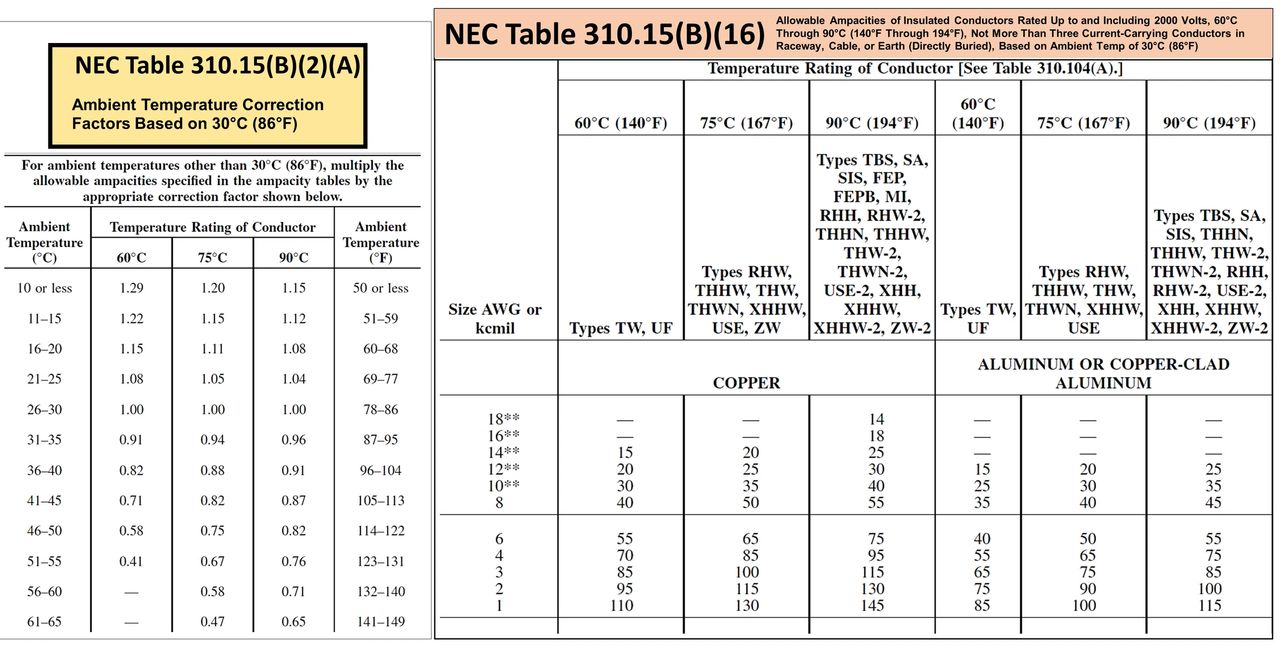
For those that aren’t familiar with residential or commercial wiring, a quick note on how much to load the circuits. The National Electric Code (NEC) essentially requires that each circuit have the ability to carry 125% of the continuous load. So if we have a 20A circuit, that is our theoretical 125%, which puts the continuous load at 16A (16A x 125% = 20A.) Head math shows that 16A is 80% of 20A, hence the 80% rule. After we determine the size of the circuit (i.e. 20A) we then reference the NEC code to find the appropriate wiring gauge for the circuit. This is code for one very good reason, you don’t want to overload and heat a smaller gauge wire too much or you’ll burn it up, and burn down your structure. I’m sure many folks have seen this on the DC side with wiring from power supplies to either ASIC miners or GPUs. I’ve chosen to use 20A for most my setups, mainly due to cost of the wire (12 gauge wire is significantly cheaper than 10 gauge), but also the efficiency calculations you’ll see later on in this post.
So let’s get into the meat and potatoes of what this is all about. I’ve listed out the most common circuits you’ll find and created scenarios based off those.
20A/240V – Given the 80% rule we have 3840W available to support our L3+ units.
3840W / 1005W = 3.82, so basically we can only run 3 L3+ units with plenty of room to spare and we are getting 1,824MH/s(AVG) out of the 20A circuit.
As a side note, we can toss one more L3+ in there at the most efficient setting (see below for wattage calculation) and that puts us at a total of 3780W and 2,328MH/s(AVG).
3840W / 765W = 5.02, so now we’re up to 5 units and we’re getting 2,520MH/s(AVG) out of the 20A circuit.
BALANCED
L3+ @ 450MHz = 873W + 10W (control board) + 60W (fans) = 943W total.3840W / 943W = 4.07, so now we’re at 4 units and we’re getting 2,304MH/s(AVG) out of the 20A circuit.
30A/240V – Given the 80% rule we have 5760W available to support our L3+ units.
5760W / 1005W = 5.73, so basically we can only run 5 L3+ units with plenty of room to spare and we are getting 3,040MH/s(AVG) out of the 30A circuit.
As a side note, we can toss one more L3+ in there at the most efficient setting and that puts us just over the 30A circuit at 5790W. Promise me you’ll unplug one intake fan (-30W) and that would give us 3,544MH/s(AVG).
5760W / 943W = 6.11, so now we’re at 6 units and we’re getting 3,456MH/s(AVG) out of the 30A circuit.
50A/240V – Did you disconnect your AC or hot tub for these miners or something?
You probably are spending more money in wiring (code says you’ll need 6 gauge wiring) then you can make on this circuit in a week. With the wiring and conduit, you’ll spend close to $5 per foot. In other words, stick with 20A (12 gauge wire) or 30A (10 gauge wire), the wiring is available at your local Lowes or Home Depot and comes in Romex so it’s an easier install without needing conduit. That’s all I have on this.
In summary, efficiency is king. Running out units at 384MHz and 9.5V yields us more than an 8% gain in MH/s(AVG) in a 20A circuit and a 14% gain in MH/s(AVG) in a 30A circuit.
Individual results may vary, take it for what it’s worth, but if you have the units, keep them running efficiently and you’ll get the most bang for your buck!


 is a NC (no connect) and on the side you see some copper showing from me prying the old ASIC off.")
 with poor connection to power and ground due to me being skimpy with the solder.")