Like many of you I’ve had the displeasure of my L3+ lose a hash board, frustrating, but sometimes easily fixable.
Often times, and I mean often, you’ll find that the 14.2V boost circuit has died which leads to your hash rate dropping to nothing for that board. I’ve seen many fixes (and attempts at fixes) and talked with a lot of folks about this. Some of the crazier things I’ve seen is removing C943 (still don’t know why they removed it) and running a jumper wire all the way across the board to D1. That gets you ~12V at the boost circuit (they did remove D1 to isolate from the old circuit) however that’s not enough to get the board to work to its full potential and it’s not a clean 12V so you can cause damage to your hash board down the line if you have power spikes.
NOTE – Per the manufacturer – Before applying power for the first time, turn the output voltage adjustment screw 20 full turns counter clockwise (CCW). Several people have reported the buck converter frying on the external module and this should insure it won’t burn out on power-on. Additionally insure you adjust the voltage using a multimeter before attaching the output to your hash board.
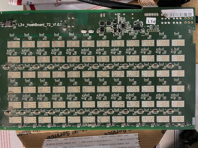
So I’ve had a hash board down for a few weeks and just now finally got a chance to take the unit down and see what we’ve got. Upon boot up the L3+ sometimes shows a missing hash board in HIVEOS (L3+_HashBoard_72_V1.6.1), as well as the stock firmware. Other times it comes up as anywhere from 2-72 chips (under ASIC status) found. I swapped cables and PS units and it still appears that way. Of note it also shows 0 for the PCB and chip temperatures, 0.00 for the MH/s (RT and avg), and strangely enough “Infinity” under W/MH.
December 1, 2021
I decided to start down the path of measuring various voltages and found the following after I inspected the 14V boost circuit (most common fault it seems:)
C1074 missing (no idea if it was ever there but the hash board did work fully at one point)
Voltage across C1072 – 11.98V
Voltage ground to L1 – 7V
Voltage across C1221 – 7.02V
So I started wondering if I’ve got a bad switching power supply in U111. I reached out to the Reddit world to see if anyone else experienced this on a hash board. I had a few folks reach out, but most the times it was to point me to the Bitmain L3+ repair guide (translated to EN.) This is a great general resource for L3+ troubleshooting, however it’s somewhat dated and really only deals with the V1.0 hash board which has different part numbering on the PCB and some completely different IC packages.
So time to get dirty again, I traced back to the DC/DC converter and found that there’s only a 7V output from there (which runs through L1), Q3/Q4 and across L2 only shows 6.94V so where do I go from here. I can’t find the V1.6.1 schematic anywhere online and can’t read the DC/DC part number to figure out what part it is. The PIC inputs are correct and it’s sending the keep alive every minute, so I think it’s somewhere between there and the boost circuit.
Update December 2, 2021
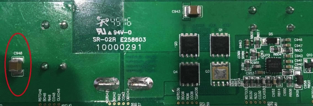
I think I have it narrowed down to before the boost circuit in the 10VDC rectifier. The big difference, other than the PCB numbering changing, is that the V1.6.1 uses a up9305W sync-rectified buck controller for the 10VDC and the older versions (1.5 and below) use the LM27402. Completely changes the circuit so the older schematics don’t help. Somehow either the up9305W is bad, or possibly a res or cap. I also verified the Schottky barrier rectifiers (MBR540MFS) on the output of the 10VDC circuit. Q1 and Q5 are tied between 12VDC and 10VDC (output) and Q3 and Q4 are tied between GND and 10VDC (output.) These then run through L2 before hitting the 14VDC boost circuit as well as other components.
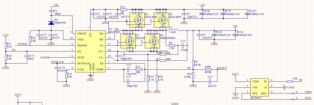
Here’s a sample of what the circuit design should look like on the V1.6.1 version hash board, and the 10VDC should be generated by the internal Vref x (R1+R2)/R2.
(*From the data sheet) The output voltage can be programmed to any level between the reference voltage VREF up to the 90% of VIN supply. The lower limitation of output voltage is caused by the internal reference. The upper limitation of the output voltage is caused by the maximum available duty cycle (90% typical). This is to leave enough time for over current detection. Output voltage out of this range is not allowed. A voltage divider sets the output voltage (refer to theTypical Application Circuit on page 3 for detail). In real applications, choose R1 in 1kΩ ~ 10kΩ range and choose appropriate R2 according to the desired output voltage.
Update December 3, 2021
I decided to go ahead and install a new 14V boost circuit. This is an easy addition to the hash board, actually much simpler and cheaper than trying to replace the components on the board itself. It’s a relatively simple part to add, I used step-up boost converters I found on Amazon for just about $1 a piece.
When adding these in the key is to have a quality soldering iron as the temps needed to reflow the solder on the L2 lead is significant. Also insure you remove D1 so you isolate your new 14V boost circuit from the existing components and set Vout to 14V before soldering the wire to the D1 pad (you should solder to the D1 pad furthest away from L1.)
Now the big test, make sure you have both the power cables and comm cable to your control board attached as the processor is required to send the signal to the hash board to operate properly. Forget this step and you’ll just be chasing “ghosts in the computer.”
Did it work, well, yes now I measure 14V however that didn’t fix my hash board issue. Next step, well, I’m going back a step and will attempt to replace the sync-rectified buck controller to see if that’s causing the low voltage (7V) instead of the holy grail of 10V. It’s strange given all the faults on the board, but it’s a good next step given the fact that if the base core voltage is off, that can have a ripple effect across other components.
Update December 23, 2021
I put together a DIY test kit for the L3 and ran some diagnostics. It appears that my temperature sensor is most likely bad (flaky, which is bad.) So my next step is to replace that and see where that takes us!
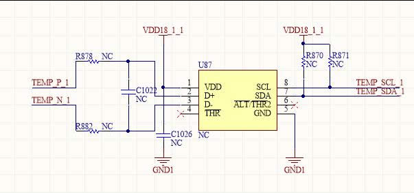
In reviewing the schematic of the temperature sensor, we can see that the TMP451 uses I2C to communicate on the hash board as well as having its own built in temperature sensor that is attached externally (pin 2 (D+) and pin 3 (D-)).
Credit – Bitmain L3+ Maintenance Guide
TEMP_P and TEMP_N are the PNP or NPN transistor in the ASIC (BM1485) itself that read the temperature. What I’m not sure of is which specific ASIC is it getting the temperature from as they operate in. I believe they use a thermal substrate transistor in one of the nearby BM1485 ASIC’s and have it wired to pin 6 (TEMP_N) and pin 7 (TEMP_P.) According the limited schematics I’ve seen they only show one representative sample of the BM1485 wiring and those pins are unconnected. I also see there are pads across the board for numerous TMP451’s, probably an enhanced feature they never implemented?
Luckily the TMP451 is in a WSON package, which makes it a complete pain to replace unless you have the right equipment and a steady hand. I suggest low temp solder paste in a syringe and a heat gun. I’ll try and video the process and post it when I’m done.
Update January 1, 2022
Finally success! I racked my brain for hours and finally decided that the buck controller wasn’t putting out the proper voltage. I inspected the PIC and since I could get some hashing I knew it was programmed properly, so I went back to PCB (printed circuit board) manufacturing 101, when it doesn’t work, rule #1 – reflow those solder joints.
I reflowed the PIC and the buck controller and viola! She’s hashing up a storm once again.
Reflow those joints, these circuit boards weren’t manufactured in the best possible environment